Diagramming
design precedents
Claridge Architects
Queen's Park Pavilion (2015)

Module 1
For M1 of Digital Design, we explore diagrams as a means of communication through a study of a precedent design.
We were to analyse and visually represent the Circulation and Thresholds of pavilions.
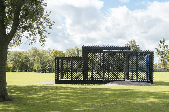
The Queen’s Pavilion by Claridge Architects from 2015 was my assigned design precedent.
Key concept
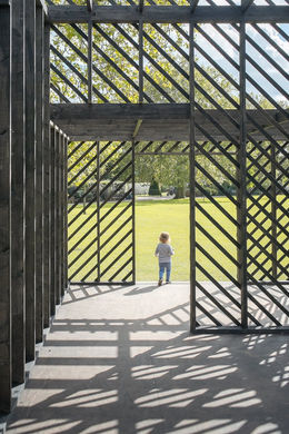
"It was important for us to create an exhibition space that was enclosed yet allowed full appreciation of the surroundings of the park when inside it," architect, Jerry van Veldhuizen of Claridge Architects.

The architects aimed to create an enclosed structure that allowed a full view of the surrounding park - a connection to the surrounding parkland is one of the leading focal points of the design.
The pavilion is a timber structure composed of three interlocking volumes. The cladding of diagonal timber battens allow airflow and light to pass through; this also creates beautiful shadow patterns in the pavilion. The external appearance of the structure was designed to evoke a sense of intrigue to draw visitors as pavilions are structures visited in passing rather than a destination.

NE Isometric View of Digitally Recreated Model in Line Work
Digital modelling
Orthographic Drawings


Rhino 7 was used to digitally create a 3D model of Queen's Park Pavilion.
Firstly, an observation of the provided reference photographs and drawings were required to understand the design and overall composition of the structure. Then, the orthographic drawings are imported into the software workspace itself and tracing is done after a rescaling. The plan is traced first as it provides the clearest layout of the entire structure to build on, while the elevation provides the height of each component. The section drawing helped to provide the information needed to build the roof structure framing. (Polyline, PlanarSrf, Extrude, Move and Scale1D were the commands used at this stage)
The sloping platform is created by using the Surface From 3 to 4 Points command and referring to both the plan and elevation drawings to discern these points. The roofing of the pavilion is formed simply by extruding a Planar Surface above the roof structure.
Lastly, to generate one of the pavilion's main attributes, the diagonal cladding that envelopes the whole structure - slats are modelled, rotated 45 degrees and spaced according to the elevation dwg., the Array command is then used to generate rows of these slanted slats creating walls that can later be attached to the structure's façade. The walls of slats are placed systematically to recreate the pavilion's cladding pattern. To cut the slats down to the varying sizes of each face, the BooleanDifference command was used.

There were some inconsistencies between the section provided and the example model drawing, however, ultimately, the example model was used as the leading guide in completing the structural components of the pavilion (numbers and direction of battens of the roof structure).

DIAGRAMS
Circulation

-
Circulation – how people move through and interact with architecture.
-
The illustrated circulation paths show the potential changes in movement according to the design and experiences of the pavilion
-
a more direct movement through the transitional spaces,
-
longer lingering in the sheltered area,
-
a heightened sense of intrigue as overlapping corners and the intersection of volumes (internal partitions) are encountered,
-
and exploration as the ever-changing views of the park is discovered at each turn.
-
-
This is reflected in the density analysis as less activity would occur by the entryways or transitional spaces of the structure.
Threshold
-
Thresholds – the boundary between places that signifies a separation between two different spaces.
-
The cladding and sloping platform form the thresholds that define the pavilion in and of itself, while
-
The thresholds inside the pavilion are established through the framing which allows for openings between the volumes and the internal partitions created by its intersections.
-
The variation of size also distinguishes the three cuboid volumes, creating a suggestion as to its intentions of use. The different scenes and senses as one enters each cube/room create a soft threshold in this pavilion.
-
The two smaller cubes make up the pavilion’s in-between spaces, acting as transitional spaces between the park and the structure, while the bigger cube makes up its main area where most activity can occur.

SECTIONAL PERSPECTIVES - SPATIAL PROGRESSION
DETAILS
Summary
-
The pavilion is experienced as a place for passing and not as a final destination for visitors of the park, and so an intriguing external appearance was necessary to draw in visitors.
-
The permeability of the structure's envelope provides changing views as you enter each room/cuboid volume, which instigates exploration.
-
Additionally, the overlapping internal partitions create different layers of transparency; the combination results in various circulation patterns, as each visitor may discover particular interests through their journey.


